What is Turning (Lathe)?

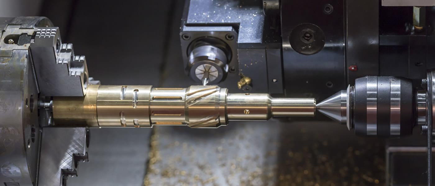
The turning process uses a spindle (or lathe) to rotate a part while tools move past it to remove material. There are various common tool and insert shapes for turning, grooving, and boring, as well as drills, taps, and reamers. Because the material is rotating in this process, turned features are always symmetrical around the center of rotation.
A standard lathe has 2-axis control. The X axis is related to part diameter, and the Z axis moves along the length of the part. Some machines also have sub spindles, which can move forward to pick up the part when it is being cut off. Then the back end of the part can be machined as well for a finished part in one operation. A common addition to turning machines, is live tooling, which is often accompanied by another axis, called the Y axis. Machines with live tooling are capable of performing mill operations, such as drilling cross holes, or milling flats and slots. These machines are capable of making extremely complex parts without any secondary operations.
What is Milling?

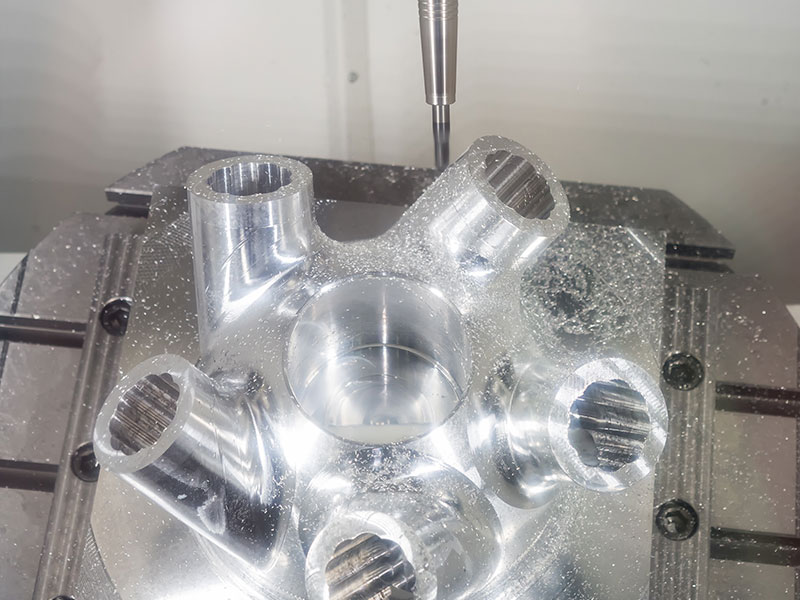
The milling process uses rotating tools to remove material. While some tools such as drills, taps, and reamers can only plunge straight into the part, the most common cutter used on a mill is called an endmill. This tool not only cuts on the tip, but it can cut on the sides, allowing complex features to be machined. There are several standard shapes, including square end, ball end, tip radius, and tapered endmills, with common sizes ranging from .005” (.127mm) to 4” (101.6mm) or larger. There are also special cutters for cutting keyways, chamfers, counterbores, and for thread milling just to name a few.
A standard mill has 3-axis control. The X and Y axis move horizontally, and the Z axis moves vertically. Each axis can be controlled individually, such as for drilling or tapping where only the Z axis moves. They can also be moved simultaneously to make free-form contours, such as mold or die components. A common addition to a 3-axis mill is a 4th axis rotary indexer. This allows machining from many more angles on a part, or machining of the full perimeter of a cylindrical part.
What is Abrasive Waterjet?

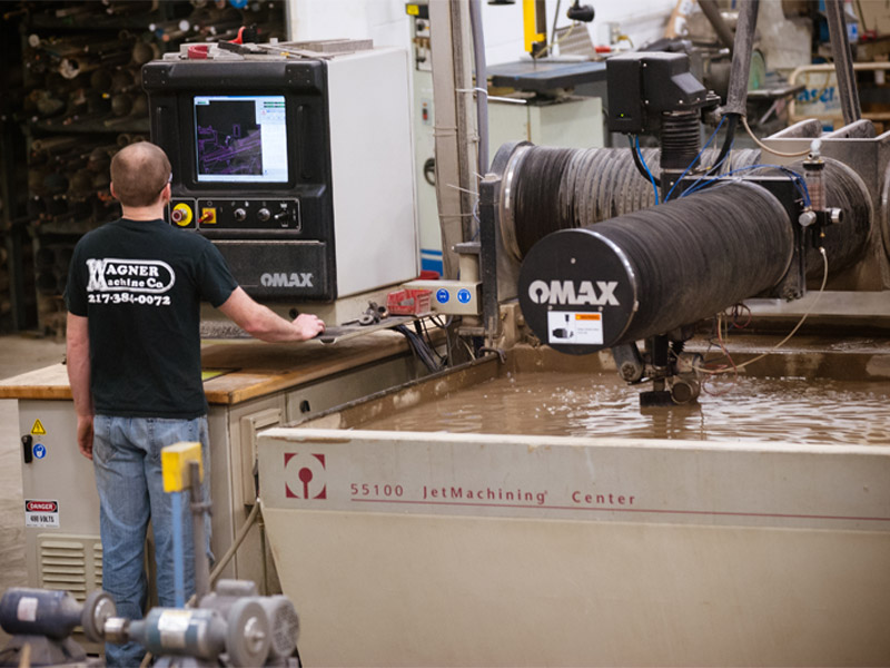
Abrasive waterjet is an extremely versatile machining process that uses ultra high pressure water, mixed with an abrasive to cut virtually any material. It is generally a 2-axis process used to cut parts from material up to 4” thick. Thicker material can be cut, but the cut speed gets exponentially slower as the thickness increases. There are 5 cut qualities to choose from. Quality 1 is the fastest and roughest cut. Quality 5 is the slowest cut with the finest surface finish. The cut qualities can be used in various combinations on a part depending on the tolerance and surface finish required in any given area of the part.
Abrasive waterjet has many advantages over torch, plasma, or laser cutting. Among them are no heat affected zone, no work hardening, almost no burr, no toxic gases(when cutting plastic or rubber),and a high quality surface finish with virtually no taper. The finish and taper are often so good that they require no secondary machining processes. The process is accurate enough that in many cases it can even cut holes on size for taps as small as 6-32. Abrasive water jet is also capable of cutting a wider variety of materials and thicknesses than any of the other processes. For example, it can cut steel, stainless steel, aluminum, plastic, rubber, urethane, foam, glass, ceramic, carbon fiber, wood, stone, and felt. It can cut all of those materials and more in thicknesses up to and exceeding 4” thick.
Although the process is just beginning to become well known, it has been in industrial use since 1982. The last 10 years have brought about some major advancements that make abrasive waterjet a practical process for an increasing variety of parts. One of the biggest improvements, and something that we use on almost every part has been taper compensation. Generally, the waterjet process leaves a very small taper on the side of cut parts. This .005”-.015”(.127mm-.381mm) taper can be virtually eliminated with the use of taper compensation. It can be used with any cut quality, so it even improves accuracy on parts that are being cut with fast settings. Another advancement is called a terrain follower. This is used in conjunction with taper compensation to ensure that the nozzle is always the same distance from the material. It helps avoid crashes, and it improves accuracy even further.
What is Wire EDM?

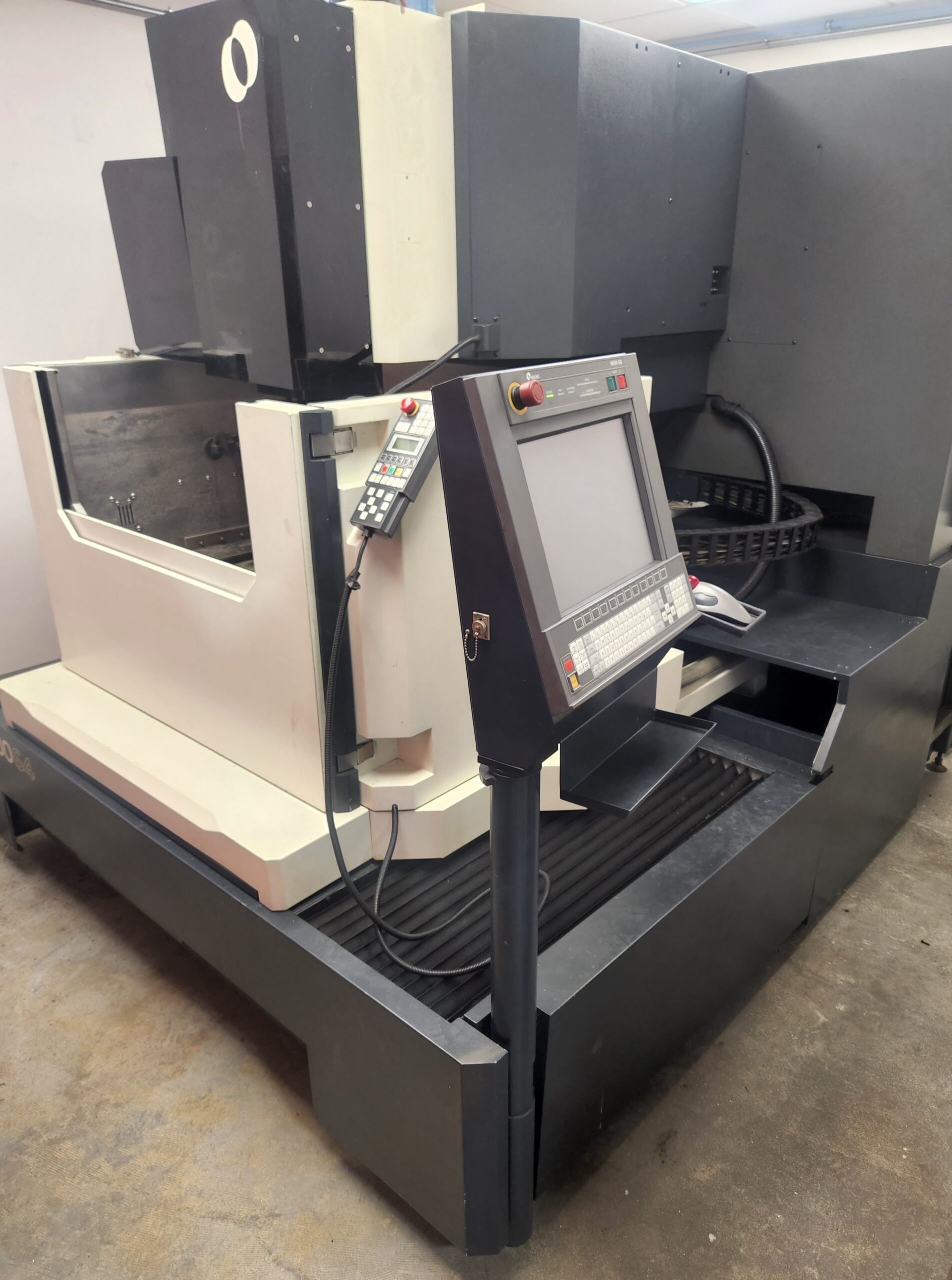
Wire EDM (Electric Discharge Machining) is a thermal machining process that uses an electrically charged thin brass wire as an electrode to cut any material that will conduct electricity. Because there is no mechanical force used to remove material, EDM is considered to be a non-conventional machining process. The wire never actually touches the material being cut. Instead, the current between the wire and the material creates a plasma that vaporizes the material being cut. During the process, the wire is also eroded, so new wire is constantly run past the part, and cannot be re-used. The process uses a dielectric fluid, usually deionized water, to flush away the small particles removed from the part and the wire, as well as for cooling.
Wire EDM is a relatively slow process, but it has unique advantages over other processes. One advantage is that it can cut hard materials, like hardened tool steel, or carbide. Another advantage is that it can cut complex profiles with small details through thick material that would be difficult or impossible by any other method. Typical wire diameters range from .006”-.012” (.152mm-.305mm). It is also extremely accurate. Tolerances of +/-.0005” (.013mm) can be held with a rough cut alone, and with skim cuts, it is possible to hold tolerances of +/-.0001” (.0025mm). Because there is no mechanical force being applied to the parts, it is also possible to cut extremely small and delicate parts. Although it is technically a thermal process, it is precisely controlled and focused, which allows it to cause almost no heat affected zone.
Many older machines are simply 2-axis machines, with an upper and lower wire guide holding the wire vertically. Most newer machines, however, are capable of moving the upper and lower guides independently. This allows the machine to tilt the wire. This is often used to cut tapered relief at a specified angle for die blocks, and is considered 2-1/2-axis. Some machines can also move the top and bottom in completely different shapes, for example, cutting a circle on the top of the part, and a square on the bottom. This is considered to be 4-axis, and is capable of cutting even more complex parts.
